Categories
Tags
-
#Insulation Aluminium Coils
#Thick Aluminum Sheet
#2024 Aluminum Plate
#Aluminium Products Supplier
#5052 Aluminium Foil
#Household Aluminium Foil
#Color Coated Aluminium Circles
#5052 Aluminum Circle
#Aluminium Circles
#Aluminum Trim Coil
#Aluminum Cookware
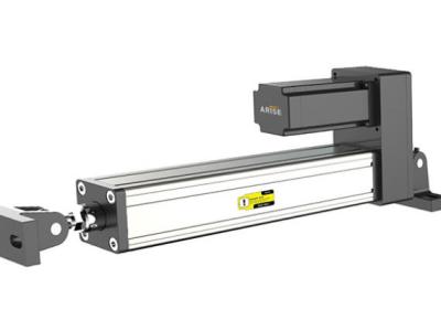
#Web Guide Actuators
#Non-Stick Coating Technologies in Aluminium Cookware
#Cigarette Packaging Aluminium Foil
#Patio Benches
Archives
Installation Best Practices for Web Guide Actuators
-
A web guide system is only as reliable as its installation. Proper installation of the guide actuator—the mechanical component that physically moves the web—is critical for achieving the desired precision, responsiveness, and longevity. Whether you're integrating a new system or upgrading an existing line, following industry best practices during installation will maximize performance and minimize future issues.
1. Pre-Installation Planning and Assessment
Understand the Web: Analyze the material characteristics (tension sensitivity, width, surface texture) and the process requirements (speed, accuracy, environmental conditions).
Select the Correct Actuator Type: Choose between pneumatic, electric, or hydraulic actuators based on required speed, force, and control precision. Ensure it matches the sensor and controller specifications.
Review Mechanical Drawings: Verify mounting locations, clearances, and integration points with existing machinery.
2. Rigid and Secure Mounting
The actuator must be mounted to a structurally rigid base. Any flex in the mounting frame will be interpreted as web wander by the sensor, causing over-correction and instability.
Use appropriate fasteners and brackets. The actuator often generates significant lateral force; mounting must withstand this without shifting.
Ensure the actuator’s plane of motion is perfectly parallel to the desired web path. Misalignment here can induce unwanted tension variations or web scratches.
3. Precise Alignment with the Sensing Point
The guide actuator should be positioned as close as possible to the point of control (where the sensor is located). The distance between them creates a "dead zone" where corrections cannot be made, reducing accuracy.
For center-guided systems, carefully align the pivot point with the sensor’s reference line. For surface-guided systems, ensure the pivot or steering roller is correctly positioned relative to the sensing edge.
4. Integration with Web Path Geometry
Follow the 10-to-1 Rule: For optimal correction, the distance from the guide roller to the pivot point should be at least 10 times the web width. This provides sufficient mechanical advantage for smooth, effective steering.
Install the actuator in a section of the web path with low web tension, if possible. High tension makes the web resistant to lateral movement, forcing the actuator to work harder and reducing sensitivity.
5. Electrical and Pneumatic Connections
Electric Actuators: Use shielded cables for motor and feedback signals. Route power cables separately from signal cables to prevent electrical noise interference. Secure all connections and provide strain relief.
Pneumatic Actuators: Install clean, dry, and regulated air supply lines. Use quick-response valves close to the actuator for faster correction cycles. Ensure all fittings are tight and leak-free.
Connect the actuator to the controller as per the manufacturer’s wiring diagram, paying close attention to feedback device connections (e.g., potentiometer, LVDT).
6. Calibration and Initial Setup
After mechanical installation, manually center the actuator using its manual override or setup mode before powering the system.
Perform the controller’s autotune or manual calibration routine with the web running. This sets the system gain and response parameters for your specific material and speed.
Set initial limit parameters to prevent the actuator from over-traveling and damaging the web or machinery.
7. Safety and Maintenance Accessibility
Install physical guards if the actuator presents a pinch point. Ensure emergency stop circuits are integrated.
Leave adequate space around the actuator for easy access to lubrication points, connection ports, and for future maintenance or inspection.
Conclusion
A meticulous approach to installing web guide actuators lays the foundation for a stable, high-performance guiding system. By investing time in proper mounting, alignment, and integration, packaging operations can achieve the promised benefits of reduced waste, improved quality, and uninterrupted production—ensuring a rapid return on investment and long-term operational reliability.