Categories
Tags
-
#Portable Oil Purification
#6000LPH Transformer Oil Purifiers
#Mobile Dry Air Compressor
#Transformer Vacuum Pumping
#Vacuum Pumping Systems
#Single Stage Transformer Oil Purification Plants
#Transformer Oil Regeneration Machine
#Transformer Oil Dehydration Machines
#Lube Oil Purifiers
#Transformer Oil Degassing
#Two-Stage Vacuum Pumps with Roots Pump
#Transformer Oil Filtration
#Hydraulic Oil Purifier
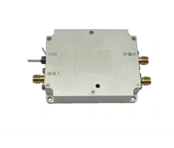
#AOM Driver
Archives
Designing a Low-Noise AOM Driver for Precision Optics
-
In demanding applications like quantum computing, atomic clocks, or gravitational wave detection, the performance of an acousto-optic modulator (AOM) system is pushed to its limits. Here, the laser's phase stability, intensity noise, and spectral purity are paramount. The design of the AOM driver—the electronic heart of the system—becomes a critical engineering challenge. A poorly designed driver can introduce noise that sabotages the entire experiment. Designing a low-noise AOM driver requires a holistic approach targeting every stage of the RF signal chain.
Prioritizing Low Phase Noise and Frequency Stability
The spectral purity of the RF signal directly impacts the phase and frequency stability of the diffracted laser beam. Excessive phase noise from the driver broadens the laser spectrum and can ruin interferometric sensitivity.
Design must begin with an ultra-low phase noise crystal oscillator as the frequency reference. A temperature-compensated (TCXO) or oven-controlled (OCXO) oscillator is often essential. The subsequent synthesis and amplification stages must preserve this purity. This involves using high-quality, shielded voltage-controlled oscillators (VCOs), low-noise phase-locked loop (PLL) design, and minimizing the contribution of power supply noise to the oscillator circuits.
Implementing Robust RF Amplification and Shielding
The oscillator's signal must be amplified to the watt-level powers (typically 1-10W) required by the AOM. This amplification stage is a major potential source of added noise and instability.
A class-A linear amplifier topology is preferred for its low distortion and reduced amplitude modulation (AM) to phase modulation (PM) conversion. Nonlinearities in class-AB or class-C amplifiers can translate power supply ripple or amplitude noise into harmful phase noise. Furthermore, rigorous RF layout practices are non-negotiable: proper impedance matching, use of microstrip lines, and extensive shielding of all RF sections are required to prevent signal leakage, pickup, and oscillations that manifest as noise.
Ensuring Exceptional Power Supply Cleanliness
The ultimate noise floor of an AOM driver is frequently set by its power supply. Every ripple, spike, or transient on the DC rails can modulate the RF output, creating sidebands on the laser frequency and increasing intensity noise.
Design requires low-noise, linear regulation for the sensitive oscillator and early-stage circuits. For the power amplifier stage, switching regulators may be necessary for efficiency, but they must be followed by high-performance linear post-regulators and extensive pi filtering. Careful grounding schemes—often star-point grounding—must be employed to avoid ground loops that inject mains-frequency noise. Critical components may even require dedicated, isolated regulators.
Integrating Precision Control and Monitoring
A low-noise driver must offer clean, stable control interfaces. The analog voltage input for amplitude control (modulation) should be buffered and filtered to prevent external noise from coupling into the RF path.
Digital control lines (for enable/disable, frequency selection) must be opto-isolated or carefully routed to prevent digital switching noise from contaminating the analog RF domain. Incorporating directional couplers and RF power detectors with calibrated monitor outputs allows for real-time feedback and system diagnostics, enabling closed-loop power stability without compromising the core signal integrity. This holistic focus on every potential noise pathway is what separates a standard driver from one capable of enabling groundbreaking precision optics.